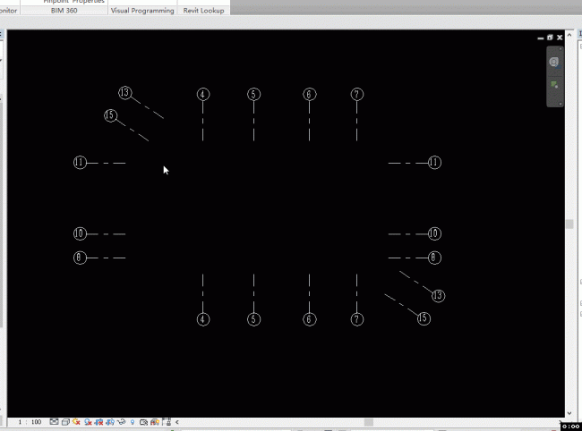
通过Revit二次开发实现对平行轴网的快速标注。交互操作是框选轴网->点选尺寸标注出现的位置->生成两道尺寸标注。
要达到设想的结果一些地方需要特殊考虑:
框选操作容易误选轴网,起码要把与所选轴网不平行的轴网过滤出来。选用了第二步操作所选点的最近轴网作为轴网平行的参考基准。遍历所有框选的轴网,如果轴网与基准轴网的向量相同或相反,则判定为平行轴网;
外侧的尺寸标注需要标识最外侧的两根轴网,取得外侧两根轴网的方法也比较简单,遍历轴网,判断另外的轴网是否都在这根轴网的左边,或者都不在这根轴网的左边,即可获得最外侧的两根轴网;
在不同的视图比例下,尺寸标注的字体高度是不一样的,所以需要读取字体高度,根据当前视图的比例,计算出内侧尺寸标注的合适位置。
以下代码:
 class QGridDimension : IExternalCommand
 {
 public Result Execute(ExternalCommandData commandData, ref string message, ElementSet elements)
 {
 UIDocument uidoc = commandData.Application.ActiveUIDocument;
 Document doc = uidoc.Document;

 //获取轴网类型
 DimensionType dimType = null;
 FilteredElementCollector elems = new FilteredElementCollector(doc);
 foreach (DimensionType dt in elems.OfClass(typeof(DimensionType)))
 {
 if (dt.Name == "轴网尺寸标注")
 {
 dimType = dt;
 //dimensionGrid(uidoc, dt);
 break;
 }
 }
 if (dimType != null)
 {
 Document document = uidoc.Document;
 IList<Element> grids = uidoc.Selection.PickElementsByRectangle(new GridFilter(), "框选轴网");
 if (grids.Count > 1)
 {
 XYZ selPoint = uidoc.Selection.PickPoint(ObjectSnapTypes.None, "选择尺寸定位位置");
 View activeView = uidoc.ActiveView;

 ReferenceArray referenceArray1 = new ReferenceArray();
 ReferenceArray referenceArray2 = new ReferenceArray();
 //获得最靠近选择点的轴网为参照基准
 List<Grid> lineGrid = new List<Grid>();
 Line referenceLine = null;
 double dis = double.MaxValue;
 foreach (Grid g in grids)
 {
 double d = g.Curve.Distance(selPoint);
 Line line = g.Curve as Line;
 if (line != null)
 {
 lineGrid.Add(g);
 if (d < dis)
 {
 referenceLine = line;
 dis = d;
 }
 }
 }
 //获得内侧尺寸标注的引用
 foreach (Grid g in lineGrid)
 {
 Line line = g.Curve as Line;
 if (line.Direction.IsAlmostEqualTo(referenceLine.Direction) || line.Direction.IsAlmostEqualTo(referenceLine.Direction.Multiply(-1)))
 {
 referenceArray1.Append(new Reference(g));
 }
 }
 //获取外侧尺寸标注的引用
 foreach (Reference refGrid in referenceArray1)
 {
 Grid g = doc.GetElement(refGrid) as Grid;
 Line line = g.Curve as Line;
 XYZ point1 = line.GetEndPoint(0);
 XYZ point2 = line.GetEndPoint(1);
 int i = 0;
 foreach (Reference _refGrid in referenceArray1)
 {
 Grid _g = doc.GetElement(_refGrid) as Grid;
 Line _line = _g.Curve as Line;
 //XYZ point1 = _line.GetEndPoint(0);
 //XYZ point2 = _line.GetEndPoint(1);
 XYZ point = _line.GetEndPoint(0);
 if (PointOnTheLeft(point1, point2, point))
 {
 i += 1;
 }
 }
 if (i == 0 || i == referenceArray1.Size - 1)
 {
 referenceArray2.Append(new Reference(g));
 }
 }
 //计算尺寸标注位置
 XYZ lineDir = referenceLine.Direction.CrossProduct(new XYZ(0, 0, 1));
 XYZ point_s = referenceLine.GetEndPoint(0);
 XYZ point_e = referenceLine.GetEndPoint(1);
 if (point_s.DistanceTo(selPoint) > point_e.DistanceTo(selPoint))
 {
 XYZ temPoint = point_s;
 point_s = point_e;
 point_e = temPoint;
 }
 XYZ offsetDir = point_e - point_s;
 double lenght = dimType.get_Parameter(BuiltInParameter.TEXT_SIZE).AsDouble();
 Line line_o = Line.CreateUnbound(selPoint, lineDir);
 Line line_i = Line.CreateUnbound(selPoint + offsetDir.Normalize() * lenght * activeView.Scale * 1.9, lineDir);
 //创建尺寸标注
 using (Transaction tran = new Transaction(document, "轴网尺寸标注"))
 {
 tran.Start();
 document.Create.NewDimension(activeView, line_o, referenceArray2, dimType);
 document.Create.NewDimension(activeView, line_i, referenceArray1, dimType);
 tran.Commit();
 }
 }
 }
 else
 {
 TaskDialog.Show("err", "未有轴网尺寸标注类型");
 }
 return Result.Succeeded;
 }

 bool PointOnTheLeft(XYZ point1, XYZ point2, XYZ point)
 {
 double r = (point1.X - point2.X) / (point1.Y - point2.Y) * (point.Y - point2.Y) + point2.X;
 if (r > point.X)
 {
 return true;
 }
 return false;
 }
 }
 internal class GridFilter : ISelectionFilter
 {
 public bool AllowElement(Element elem)
 {
 if (elem is Grid)
 {
 return true;
 }
 return false;
 }
 public bool AllowReference(Reference reference, XYZ position)
 {
 return true;
 }
 }

微信公众号:xuebim
关注建筑行业BIM发展、研究建筑新技术,汇集建筑前沿信息!
← 微信扫一扫,关注我们+

 BIM建筑网


评论前必须登录!
注册